News
How the cryogenic air separation process works?
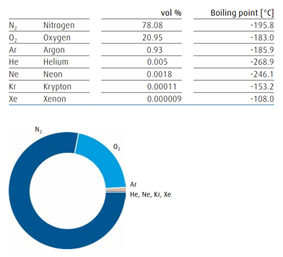
Composition of ary air Liquefaction process of air separation
To enable air to be separated into its constituents by means of rectification – the actual separation process – a large part of the air volume used must be liquefied. A gas can only be transformed into a
liquid state at temperature and pressure conditions below those of
its critical point.
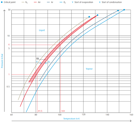
The critical point of air is Tcrit = -140.7 ºC (132.5 K) and Pcrit = 37.7 bar.
In other words, air can be liquefied only at temperatures below -140.7 ºC
(132.5 K).
The vapour pressure curve illustrates the allocation of temperatures and
pressures at which a gas condenses or a liquid evaporates.
→ Air below atmospheric pressure (1 bar) must be chilled
to -192 ºC (81.5 K) before condensation sets in
→ Air below a pressure of 6 bar must be chilled
to -172 ºC (101 K) before condensation begins
The boiling point and condensation conditions of gas mixtures such as air
are not identical. A condensation line and a boiling point line delineate the
boiling point range.
Vapour pressure curves of atmospheric gases
Air separation by rectification.
Rectification is synonymous with countercurrent distillation. This special distillation separation process enables the individual components of a mixture to be separated with a high purity combined with a good yield, even when their boiling points are relatively close to each other.
A result of the different vapour pressures of the individual components (pN2 > p02), the composition of the vapour differs from that of the liquid
mixture. Correspondingly, a higher proportion of the component with the greater pressure vaporises during the evaporation process.
The vapour produced from a boiling liquid mixture of O2/N2 will thus have a higer N2 concentration than the liquid mixture from which it originates.
Accordingly, the condensate produced when an O2/N2 vapour mixture is liquefied will display a higher O2 concentration because the component
with the lower partial pressure tends to transform into liquid.
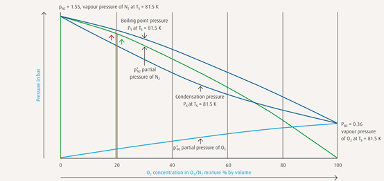
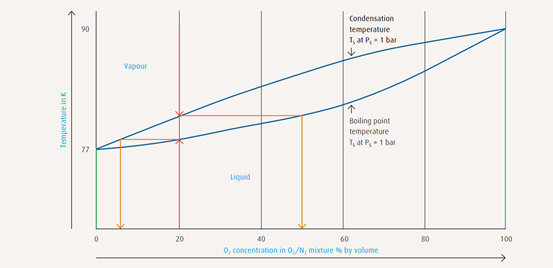
The principles of air separation.
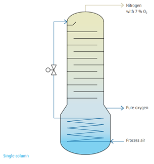
Air separation by rectification in a single/double column:
Using his air liquefaction principle as a basis, Carl von Linde constructed the first air separation plant for oxygen production in 1902 using a single column rectification system. In 1910, he set the basis for the cryogenic air separation principle with the development of a double-column rectification system. Now it was possible to produce pure oxygen and pure nitrogen simultaneously.
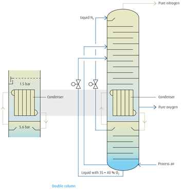
Below the low-pressure column a pressure column was installed. At the top of this column pure nitrogen was drawn off, liquefied in a condenser,and fed to the low-pressure column serving as reflux. At the top of this low-pressure column pure gaseous nitrogen was withdrawn as product while liquid oxygen evaporated at the bottom of this column to deliverthe pure gaseous oxygen product. This principle of double-column rectification combining the condenser and evaporator to form a heat exchanger unit is still used today.
Condenser/reboiler
The principle of double-column rectification is characterized through the
combination of condenser and evaporator to form a common heat exchanger unit. By this means the rectification is divided into two separate
areas with different pressures.
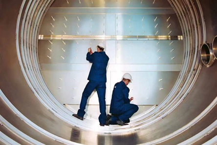
Column design.
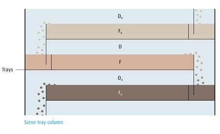
Any tray of the rectification column follows the same principle:
The O2 concentration of the boiling O2/N2 liquid mixture F is greater than
the O2 concentration of the vapour D. A certain volume of liquid corresponding to the same volume of reflux constantly flows from the tray above into the liquid mixture below with an equivalent volume flowing down over a weir onto the tray below.
The vapour Du coming from the bottom tray penetrates the liquid mixture F and has a higher O2 content than the vapour mixture D. The O2 concentration of the vapour Do rising from the upper tray is in turn less
than that of the vapour D. Thus a product rich in nitrogen is obtained inthe head of the column and a liquid rich in oxygen in the sump of the column.
Pure argon production by rectification
Modern process
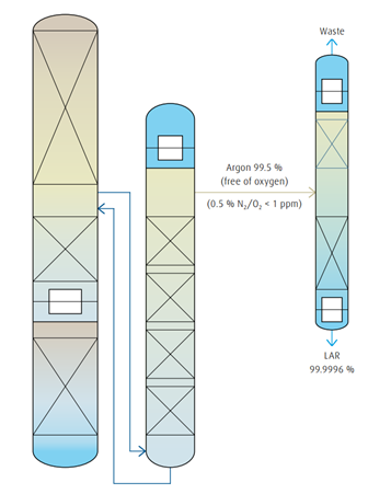
Within the so-called argon belly – the area in the low-pressure column where the argon concentration is at a maximum (approx. 10 %) – a gas stream is fed into the raw argon column for further rectification. The remaining oxygen in this gas stream is completely removed in the rawargon column, which is also a packed column. Due to the very low pressure drop in the packing, it is possible to install a sufficient number of
“theoretical trays” required for the rectification. In the adjoining pure argon column the remaining nitrogen is removed by rectification and the pure argon is liquefied.
Pure argon production by catalytic converter
Conventional process
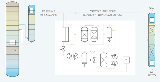
Before the technological progress in the form of structured packings was applied, a significantly more complex, process for the production of pure argon had been used. At that time, it was not possible to remove the oxygen in the raw argon column completely by means of rectification.
A percentage of 2.5 remained. This was due to a higher pressure loss through the trays, which consequently resulted in a lower oxygen concentration that was insufficient for complete rectification. An additional process step was required to remove the remaining oxygen by means of a catalytic converter using hydrogen.
Internal compression
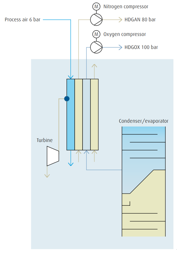
The internal compression (or liquid pumping) process allows for oxygen,nitrogen as well as argon to be compressed within the cold box by means of liquid pumps, to be evaporated and warmed up in heat exchangers,and finally to be supplied to the end user at the required pressure.
In order to evaporate and warm up the compressed liquid, a countercurrent stream of nitrogen (or air) with a higher pressure than the required liquid is required for thermodynamic reasons.
For plants that produce pressurized nitrogen, the booster and/or recycle nitrogen compressor also provide the countercurrent stream for evaporation. With this method complex external oxygen compression is no
longer required, thus plant operation and maintenance have become considerably easier and more reliable. Furthermore, the risk of dangerous hydrocarbon enrichment in the condenser is avoided because liquid oxygen is continuously withdrawn from the condenser and pumped into the heat exchanger where it evaporates. Compared with the external compression system a considerably higher level of safety has been
achieved.
External compression
Conventional process
High-pressure gaseous oxygen is required for storage in pressure vessels or in high-pressure gas bottles, and for the application of oxygen in certain chemical processes. Pressures of up to 200 bar are used for oxygen storage. For chemical processes such as partial oxidation of residual oil, oxygen at a pressure of up to 100 bar is required.
A significant increase in applications in the chemical and petrochemical industries and the high requirement of plants with high capacities has led to alternative concepts with regard to the risks involved with high
oxygen pressures.
In particular, the compression of oxygen in external compressors created
problems due to the reduction of ignition temperature of organic and inorganic materials with increasing temperatures (e.g. the ignition temperature of iron/steel is reduced by more than 100 °C with a pressure increase from 50 to 100 bar). Furthermore, the required safety measures for external
compression have an impact on overall investment costs.
Advanced condenser/reboiler design
Down flow condenser
→ Used instead of two-storied or multi-storied bath condensers
→ No-condenser vessel
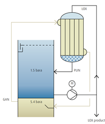
→ LOX recycle pump for reflux is necessary
→ Oxygen pipework is necessary
→ Suitable for ASUs with internal LOX compression
→ Suitable for Medium&large ASUs
→ Energy-saving solution
Combi condenser
→ Combination of bath condenser plus down flow condenser
→ No oxygen pipework
→ No LOX recycle pump in connection with Kr/Xe production
→ LOX recycle pump for reflux is necessary without Kr/Xe production
→ Suitable for ASUs with internal LOX compression
→ Suitable for large ASUs
Supply chain.
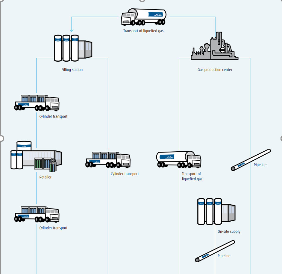
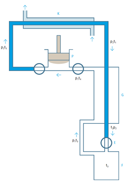
Typical cryogenic air separation process.
Cryogenic air separation process for the production of gaseous pure oxygen and nitrogen with internal compression and the production of liquid oxygen, liquid nitrogen and liquid argon:
1 Air compression
Compression of ambient air by a multi-stage turbo compressor with inter- coolers at a supply pressure of approx. 6 bar. Removal of dust particles by a mechanical air filter at the inlet of the compressor.
2 Air cooling and & purification
Cooling of process air with water in a direct contact cooler and removal of soluble air impurities. Chilling of cooling water in an evaporation cool-er against dry nitrogen waste gas from the rectification process. Removal of CO2, water vapour and hydrocarbons from the process air in periodical- ly loaded/regenerated molecular sieve adsorbers.
3 Low-temperature heat exchange
Cooling of process air in heat exchangers down to nearly liquefaction temperature by means of countercurrent with nitrogen waste gas from the rectification process.
4 Cold production & internal product compression
Further compression of a sidestream of process air by an air booster com- pressor. Expansion and cold production of the boosted air stream in an ex- pansion turbine. Expansion and liquefaction of a sidestream of the boosted air in a liquid separator. Evaporation and warming to ambient temperature of the pumped oxygen and nitrogen product in high-pressure heat exchangers.
5 Cryogenic rectification of air
Pre-separation of the cooled and liquefied air within the pressure column into oxygen enriched liquid in the column sump and pure nitrogen gas at the column top. Liquefaction of the pure nitrogen gas in the condenser/ reboiler against boiling oxygen in the sump of the low-pressure column. Liquefied nitrogen provides the reflux for the pressure column and (after sub-cooling) for the low-pressure column.
Further separation in the low-pressure column of the oxygen-enriched liquid within the low-pressure column into pure oxygen in the sump and nitrogen waste gas at the top.
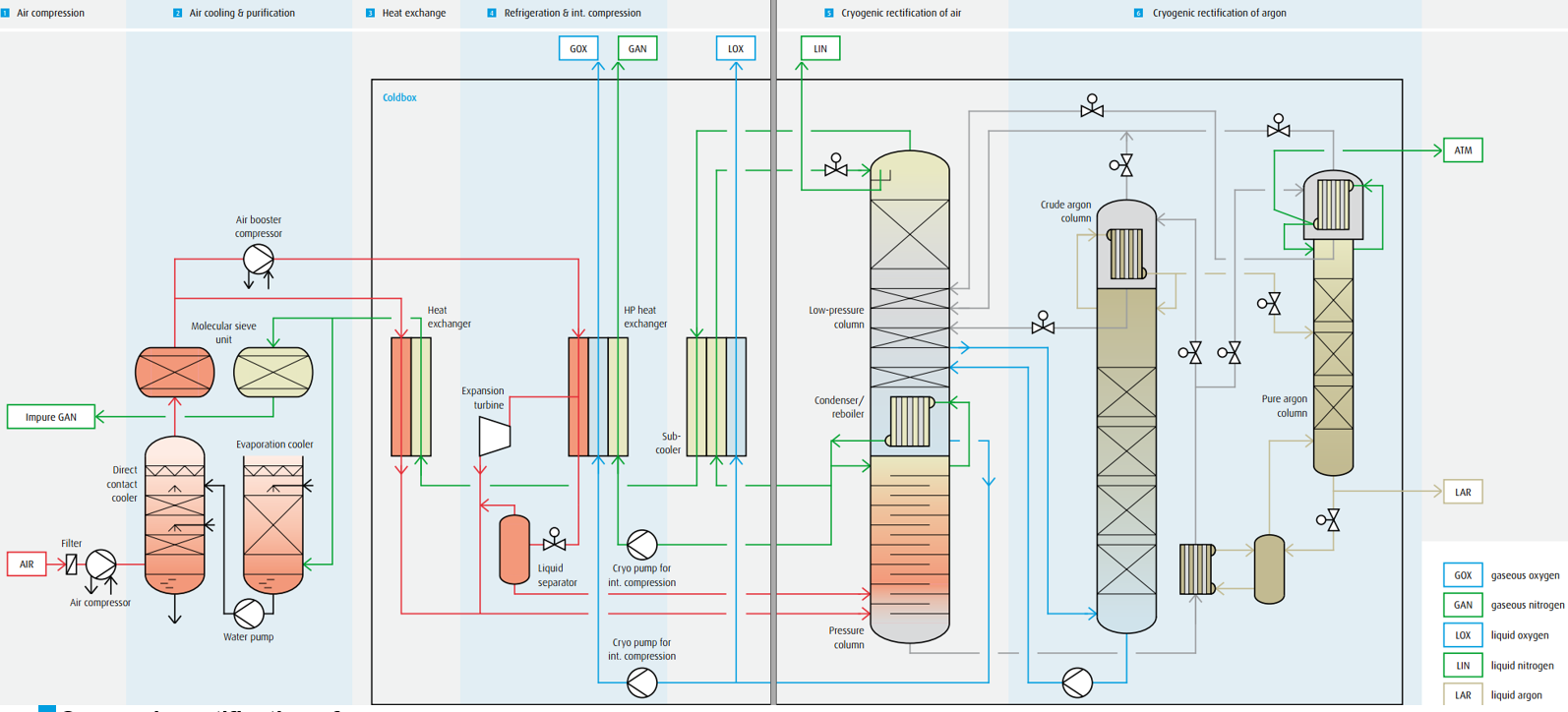
6 Cryogenic rectification of argon
Argon-enriched gas from the low-pressure column is transformed into oxygen-free crude argon by means of separation within the crude argon column.
Pumping back liquid oxygen from the crude argon column sump into the low-pressure column. Removal of the remaining nitrogen in the pure argon column.
RELATED NEWS
- How Does an Oxygen Generator Work for Industrial Use 2022-04-20
- How does Pressure Swing Adsorption work? 2022-01-25
- 10 Uses for Oxygen 2022-02-12
- Ways Nitrogen Is Used In Everyday Life 2022-02-12
CATEGORIES
LATEST NEWS
CONTACT US
Contact: Fang
Phone: 0086-180 7293 4264
E-mail: fang@hzasligas.com
Whatsapp:0086-180 7293 4264
Add: Yinhu Street, Fuyang District, Hangzhou City, Zhejiang Province, China
